


Fluid Bed Processor (Fluid Bed Dryer)
Fluid Bed Processor, Fluid Bed Dryer
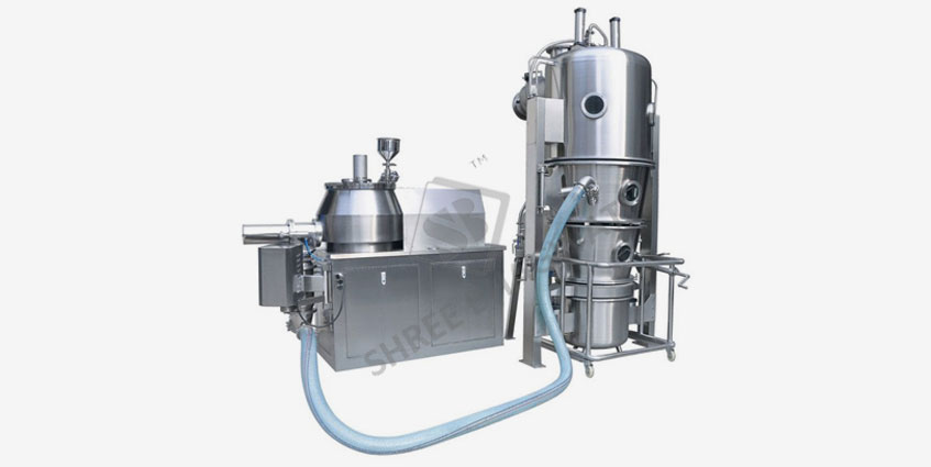
Fluid or fluidized bed dryers: Essential equipment in pharmaceutical industries, effectively reducing moisture in powder and granular raw materials through fluidization. Shree Bhagwati has adopted new concept of GMP Regulation and fluid bed technology for the production of Fluid Bed Dryer, ACG Fluid Bed Processor which yields improved performance. The drying time in the machine is much less than the conventional model. There is minimum involvement of manual labor simplified maintenance and utilize modular construction techniques to provide flexible installation options.
The Fluid Bed Processor is a two piece unit which is manufactured from SS-304 / 316 stainless steel. The process of mixing of Dry powders, Agglomeration and Drying is carried out in one unit Fluid Bed Dryer.
Fluid bed dryer finds extensive usage in pharmaceutical industries in order to reduce the moisture content of pharmaceutical granules and powder. It is also known as fluidized bed dryer. The machine has excellent gas particle constant which enables it to produce a high rate of moisture removal that results in high mass and heat transfer rates.
 Fluid Bed Processor Specification
 Features
Technical Specification of Fluid Bed Dryer
| Description | BF-30 | BF-60 | BF-120 | BF-200 | BF-250 |
|---|---|---|---|---|---|
| Capacity Of Dryer In Kgs At 0.6 Kg / Lt Bulk Density | 30-50 | 50-70 | 120-150 | 200-220 | 250-270 |
| Working Capacity Of Product Container In Liters | 50 | 100 | 200 | 335 | 420 |
| Total Volume Of Product Container In Ltrs | 100 | 200 | 400 | 580 | 760 |
| Blower Motor h.p. | 5 H.P. | 10 H.P. | 15 H.P. | 20 H.P. | 20 H.P |
| Heater Load | 18 K.W. | 36 K.W. | 60 K.W. | ------ | ------- |
| Steam Consumption | 25 KGS | 55 KGS | 110 KGS | 180 KGS | 240 KGS |
| Heating Capacity In Kcl / Hr | 11610 | 23220 | 38700 | 77400 | 96750 |
| Space Requirements Approx. | ------ | ------ | ------ | ------ | ------ |
| Length | 1550 | 1550 | 2480 | 2500 | 2700 |
| Width | 900 | 1200 | 1400 | 2150 | 1900 |
| Height With Motor | 2150 | 2650 | 2950 | 3400 | 3500 |
DESCRIPTION & OPERATION OF : Fluid Bed Processor / FBP Machine / Fluidized Bed Processing Equipment
Bottom chamber
The main function of bottom chamber is to uniformly mix hot air before allowing it to enter in to the product container. Container and bottom chamber are having suitable flange to fit inflatable silicon seal to achieve leak-proof operation. (MOC SS 304)
Product container
- Perforated Plate: Having number of holes of equal diameter for uniform distribution of air through the product.
- Bottom sieve: The Dutch weave sieve acts as product retaining filter.
- Sight glass: To view the movement of product.
- Triclover for sensor: Facilitates mounting of product temp. Sensor, which measures product temperature.
- Sampling Device: A device for easy withdrawal of sample during process on.
- PZ sieve (Dutch mesh): Detachable PZ sieve facilitates easy washing and cleaning.
- Trolley: Product container is mounted on the mobile trolley for easy movement having PU wheels. (MOC SS 304)
Spray and retarding chamber
- It consists of expansion zone where spray nozzle is fitted and upper portion of the filter housing where filter bag assembly is placed.
- For the vertical adjustments of the nozzle, multiple height mountings at spray port are provided.
- Two sight glasses are provided. The lower one for observation of the spray jet and the upper one for filter-locking devices.
- For better visibility a light source is provided.
- Main chamber & product container having flange to fit Inflatable seal to achieve leak proof operation.
- Explosion duct: It works as a safety valve for the unit. When pressure increases above 2 bars, disc opens and pressure is released to atmosphere.
- In the event of explosion, a limit switch will be activated upon opening of explosion disc which shuts down the machine operation.
Finger Bag Unit
- Top filter ring: It holds the top end of the filter bag. This ring is attached to the shaking pneumatic lock assembly. (MOC SS 304)
- Bottom filter ring: The other end of the filter bag is attached to this ring through a clamping assembly. (MOC SS 316)
- Filter Bag: A filter bag is used to retain the fines. (PC Satin)
Filter Bag Shaking Cylinder
- This cylinder is to shake the filter bag at predetermined intervals to bring back the fines in to product container which are deposited in the bag during the process. Shaker pneumatic assembly holds the bag assembly.
Spraying System
- Spray Pump with Trolley: Spray pump is use to convey the binder solution from tank to the spray nozzle. Spray pumps speed adjustment can be done through operating panel or on the spray pump. It is mounted on the separate SS 304 Trolley.
- Spray Nozzle: Spray nozzle is used to spray the binder solution into the fluidized bed. For the vertical adjustments of the nozzle, multiple height mountings at spray port are provided in the retarding chamber. (MOC SS-316L)
Damper OR Control Flap
- Damper at inlet: It is located on the bottom chamber flange and prevents water from entering in the inlet duct during washing and also prevents suction of air from inlet air handler during suction charging. ON / OFF Type (MOC SS-304)
- Damper at Outlet: It controls airflow depending on product & process requirement with the help of proportionate valve through I/P. (MOC SS-304)
Blower
- The airflow through the machine is produced by the blower by creating suction. It is located at the outlet end.
- The selection of the blower depends on the airflow requirement. (MOC MS/AL. WITH EPOXY PAINTED & SPARK PROOF CONSTRUCTION)
Inlet Air Handling Unit
- Standard AHU is a double skin 50mm PUF insulated unit having SS304 sheet inside & MS powder coated sheet outside. It comprises of steam heater with counter flange, Face & Bypass system, EU4 (10 micron), EU7 (5 micron) Filter & EU14 (HEPA) and ON/OFF type steam Valve.
- Support Column frame: It supports the Operating control panel, Pneumatic control panel, Main Body housing and also the bottom chamber. (MS WITH SS 304 CLADING)
A) Inlet temperature measurement: Provision is made at inlet duct for measuring inlet temperature of the air. Required temperature can be set through PLC. As the temperature reaches the set value the face portion closes gradually.
B) Outlet temperature measurement: Provision is made at outlet for measuring outlet temperature of the air. As the inlet air passes through the product, heat is transferred to the product and the process air leaves through the outlet filter. The temperature of this air is indicated on PLC.
Operating Control Panel (Basic PLC System)
- Control panel (mounted on the lateral support) is made of SS 304. A 10” colour HMI is installed to operate the machine with through PLC.
- One emergency push button is given for shutting the machine off in any unlikely event. (In case of flameproof machine it is mounted separately on the lateral support)
- One pressure gauge for monitoring pneumatic pressure for machine operation
- Two Pressure gauges to monitor sealing pressures
- Gauges to monitor differential pressure across product / bottom screen
- One manual setting knob with dial gauge for adjusting atomization air pressure
- Pneumatic switch and indicator for filter bag locking
The following functions will be operated through the PLC:
- Inflate / Deflate filter sealing
- Inflate / Deflate container sealing
- Exhaust air temperature – set, actual, min & max
- Product air temperature – set, actual, min & max
- Inlet air temperature – set and actual with PID control
- Pneumatic filter Bag shaking device Auto/ Manual
- Filter shaking interval
- Duration of filter shaking
- Main Air Pressure Set Min. Level.
- Process on/off
- Heater on/off
- Spray on/off
- Different safety alarms & safety interlock
- Recipe parameters, Batch code, Operator code, Product code, Batch parameters, Process parameters like Temperature, Blower speed, Process time etc
Electric panel
All the electrical control components like contactor, relay & transformer etc. are mounted inside the M.S. Power Coated panel which is placed in the service area.
Pneumatic panel
- All pneumatic components are mounted inside the S.S.304 panel and fitted on support column of the machine.
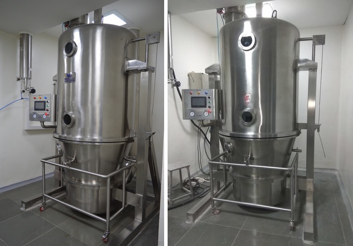
FLUID BED PROCESSOR - GMP MODEL Fluid Bed Processor / FBP Machine / Fluidized Bed Processing Equipment
Standard Scope of Supply
Basic Machine with SS 316 Product Contact Parts & other non contact parts made of SS 304, AHU Double skin with PUF insulated (with steam heater), Face & Bypass system, EU4 (10 micron), EU7 (5 micron) & EU14 (HEPA Filter) Blower with Lather Bellows, Pneumatic Shaking, Pneumatic operated Inlet Damper ON/OFF, Pneumatic operated Outlet Damper 0% to 100% through I/P, PLC based operations with 10 colour HMI, Finger Bag Lifting & Lowering by Rod Less Cylinder, Finger Bag & Product Mesh DP Indicator & Non FLP Motor. All Inflatable Seals are of Transparent Silicon. Peristaltic Pump with trolley. Spray Nozzle, All Electricals & Pneumatics are of reputed brand & Solid flow monitor (Broken bag detector)
Salient Features
- The process unit is two piece, made of stainless steel of SS-304 GRADE.
- All process contact parts are made of SS-304 grade.
- The finish employed externally will be all welds ground back and polished into the surrounding materials.
- All of the external surfaces of the Dryer and all non contact/sight parts will prepared with a uniform fine texture matt finish.
- All of the product contact surface (SS-304) are mirror finished.
- Particular attention has been paid to reduce any source of material Entrapment by mirror polishing flush all welds to create crevice free profiles both internally and externally.
- The expansion chamber containing the filter finger bags & dished end are made of single piece construction from SS-304 / 316 quality steel. Below that is the retarding chamber made out of S.S. 304 Retarding chamber is locked with the explosion chamber by means of clamps.The length of the retarding chamber is such designed , thereby providing extra large heat exchange are which exposed each and every particle or the charged batch in the Fluidized air resulting in instant drying.
- Specially designed base is provided for air vortex effect and to give added strength.
- A central drain is provided in the base to release wash water.
- Single Pot Technology for mixing, granulating, drying & coating.
- Replaces a number of conventional machinery like RMG, Multi mill, FBD and Blender.
- Shorter cycle time resulting in increased productivity.
- Yield approaching 99% with negligible handling losses due to single pot.
- PLC controls ensure high degree of process of control parameters ensuring batch-to-batch reproducibility.
- In a FBP, the powder particles are fluidized and then granulated by effective top spraying mechanism of binder.
- FBP ensures reduction in manpower, utility, space etc. Hence there are benefits like less utility consumption, less material handling, redction in dust level, reduction in product exposure to the environment and operator’s exposure to the product.
- Most hygienic and minimum cross contamination problem.
- Broken Bag Detector ensures no product loss.
Bowl / Pro Duct Container
- Product bowl is a conical shaped manufactured form SS-304 grade stainless steel having stainless steel mesh support along with fine finish air mesh.
- The product container Trolley is of Tubular construction made form SS-304 pipe mounted on polypropylene castor wheel (2nos fixed & 2nos. Swivel for maneuverability ) which imparts rigidity to carry the product container with the charged load.
- The batch loading capacity is always higher in case of Shree Bhagwati Pharma Machinery Fluid Bed dryer, because of better fluidisation by varying the frequent shaking of the finger bags. Shaking period vary depending on the nature of products.
Rubber Gasket
A solid ‘D’ shaped food type silicon rubber gasket is provided in the groove of the flanged joint (between the product container and the retarding chamber) to prevent any leakage of air with fines during operation.
Uniform Lifting Of Container
Product container is lifted by specially designed arrangement with the help of one centrically fitted pneumatic cylinder which ensures uniform lifting throughout the periphery of the container which ultimately gives uniform upward pressure to the solid ‘D’ shaped Rubber Gasket, thereby preventing any leakage during operation.
Auto Shaking Device
Pneumatic cylinder is used for auto shaking device of the finger bags is mounted on the body and is fitted with a wire rope made out of S.S. 304 guided by pulleys thus rendering the shaking extermely efficient. It also brings down the finger bags to such a level that these can be inspected very easily form the bottom of the retarding chamber. If the shaking is not efficent , the particles will be retained in the finger bags and there will be no proper fluidisation resulting in formation of lumps in the products container.
Air Handling Unit
Blower and filter with heating arrangement are housed in the rear chamber . They can also be housed the services zone to avoid sound pollution as well as to avoid interference of the maintenance people in the production zone.
Blower
- Centrifugal type blower fan with dynamically balanced impeller and backward curved blades.
- All Stainless steel construction.
- Direct coupled non—flameproof electric drive. Anti – vibration mounting and independent sub-supportframe.
Air filter
Free standing unit constructed from aluminium anodisedl frame work (SS-304) with doubled skinned panels. All wallpanels are cross based for added strength . Quick release panels provided for inspection and maintenance access.
The air intake section has a full face external flange for attachment of angle intact, or and extended inletair duct.
Inlet system comprssiong of 20Micron washable filter. followed by 5 micron prefilter, then pass through , heating coil section containing a full air duct steam operated heater battery, constructed with stainless steel tubes and headers and a steel casing (SS-304). The moving process air passes through the steam heater to achieve the desired temperature. to match the inlet to the processing unit.PT 100 temperature sensing probe will be fitted into the air Transtion duct and will be connected upto the control panel.
Explosion Vent
As per international practices the equipment is provided with a rapture disc as measures of explosion Vent, Tested at 2 Bar pressure, mounted on the side of the dryer.
Earthing Device
A std designed earthing device spring type is provided with the dryer however intrincically safe earthing device with low voltage relay is also available.
Electro Pneumatic Control Panel
A free stading steel control panel having the following controls.
- Inlet air temperature controller.
- Exhaust air temperature indicator
- Product bowl lifting & lowering valve.
- Process air Damper regulation
- Blower motor, start & stop.
- Compressed air pressure quages.
- Filter bag shaking timer
- solenoid valves etc.
Programme Logic Control System
Semi-automated and fully automated PLC and PLC / PC control system are available for selection at an appropiate level of additonal cost. (OPTION)
Fluid Bed Dryer and Rapid Mixer Granulation

ACG Fluid Bed Processor , Fluid Bed Coater


