


Tube Heat exchanger – Shell Heat exchanger, shell and tube heat exchangers
Tube & Shell Heat Exchanger
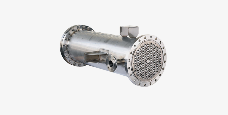
Heat Exchangers (Shell& Tube Type)
Application of Tube Heat exchanger – Shell Heat exchanger, shell, and tube heat exchanger:
Heat Exchangers find extensive uses in chemical, petrochemical, oil & gas, power generation, refrigeration, pharmaceuticals, HVAC, food & beverage processing, and pulp & paper industries. Most processing industries use the mechanism of transferring heat from one fluid to another. The heat exchanger is such a piece of equipment for transferring heat from one fluid to another fluid. Heat Exchangers are classified.
Heat Exchangers are classified depending on the transfer process between them. The shell and tube exchangers are the most commonly used heat exchangers. Amongst them, the most common types of shell and tube exchangers are:-
The Fixed tube-sheet exchanger (non-removable tube bundle): The simplest and cheapest type of shell and tube exchanger is the one with a fixed tube sheet design. The tube sheet is welded to the shell and no relative movement between the shell and tube bundle is possible in this type of exchanger.
Removable tube bundle: In this, the tube bundle may be removed for ease of cleaning and replacement. A removable tube bundle exchanger can further be categorized into a floating head and a U-tube exchanger.
Floating head exchanger: It consists of a stationary tube sheet that is clamped with a shell flange. At the opposite end of the bundle, the tubes may expand into a freely riding floating-head or floating tube sheet. A floating head cover is bolted to the tube sheet and the entire bundle can be removed for cleaning and the inspection of the interior.
U-tube exchanger:
This type of exchanger consists of tubes that are bent and rolled back into the tube sheet. This means that it will show some tubes at the center of the tube bundle. This Heat-exchanger system consisting of a bundle of U tubes hairpin tubes surrounded by a shell outer vessel where one fluid flows through the tubes, and the other fluid flows through the shell, around tubes.
Thermal Design Consideration:
The primary consideration for the design of heat exchangers is the flow rate of both the hold and the cold streams, their terminal temperatures, and the fluid propeller. Also the determination of heat transfer area, number of tubes, tube length, and diameter, tube layout, number of shell and tube passes, type of heat exchanger (fixed tube sheet, removable tube bundle, etc), tube pitch, number of baffles, its type and size, shell and tube side pressure drop, etc play a major role in designing this piece of machinery.
Shell:
This shell is the container for the shell fluid and the tube bundle is placed inside this shell. The main factor while choosing the shell diameter should be such that it gives a close fit to the tube bundle. The clearance distance between the tube bundle and the inner shell wall depends on the type of exchanger preferred. The Shells are usually fabricated from standard steel pipes that have a satisfactory corrosion allowance.
Tube:
While designing a compact heat exchanger, it is very common to have a Tube OD of ¾ and 1". The most congenial condition for a heat transfer is to have the maximum number of tubes in the shell to increase turbulence. The tube thickness should be enough to withstand the internal pressure along with the adequate corrosion allowance. The tube thickness is expressed in terms of BWG (Birmingham Wire Gauge) and tube outside diameter (OD). A longer tube reduces shell diameter at the expense of higher shell pressure drop. Finned tubes are also used when fluid with a low heat transfer coefficient flows around the shell side. The commonly used tube materials are stainless steel, admiralty brass, copper, bronze, and alloys of copper-nickel.
Tube pitch, tube-layout, and tube-count: Tube pitch can be explained as the shortest distance between adjacent tubes which is counted from one center of the tube to another. The pattern of placing tubes is usually square or triangular. The number of tubes that can be accommodated in a given shell ID is called tube count. The tube count depends on many factors like shell ID, OD of the tube, tube pitch, tube layout, number of tube passes, type of heat exchanger, and the design pressure.
The tube passes: The number of passes is chosen to get the required tube side fluid velocity to obtain greater heat transfer co-efficient and also to reduce scale formation. The tube passes vary from a scale of 1 to 16 and the tube passes of 1, 2, and 4 are common in application.
The Paron is built into the exchanger head known as paron plate (also called pass paron) and is used to direct the tube side flow.
Tube sheet:
The tubes are attached to the tube sheet that forms the barrier between the tube and shell fluids. The tubes can be fixed with the tube sheet using a ferrule and a metal packing ring. The tubes are attached to the tube sheet with two or more grooves in the tube sheet wall by way of tube rolling. The tube metal is forced to move into the grooves forming an excellent gate seal. This is the most common type of fixing arrangement seen in large-scale industrial exchangers. The tube sheet thickness should be greater than the tube outside diameter to make it a good seal. The recommended standards (IS:4503 or TEMA) are followed to select the minimum tube sheet thickness, selection of fluids for the tube and the shell side as the round part of the shell side and tube side fluids have considerable effects on the heat exchanger design.


